remaking echo 1 - stealth physics
how soviet math led to the first empirically stealth-optimized aircraft
I would like to preface this by saying I'm not an expert in this field by any means; I'm an average software engineer with an above-average interest in aerospace and physics. All visualizations were drawn/generated by me and code can be found in this project's github repo
black diamonds and bouncing photons
 1752308995975_bzq2ct.png
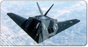
Ever since I first delved into engineering, I became entranced with arguably the most captivating aircraft ever created, the SR-71 Blackbird. The technology behind this aircraft alone is mind-boggling, and if unfamiliar I highly recommend Real Engineering's youtube video on the topic.
The SR-71 was a stealthy aircraft, to be sure, but not in the current way we understand stealth. It had clever shaping and radar-absorbing paint, but its true defense was speed and altitude. Later aircraft, namely the F-117, however, strived to be completely invisible. To achieve this, it used a completely different technique, pioneered by physics rather than engineering.
(p.s. also highly recommend the video for the nighthawk for some slightly more intuitive visualizations)
The Soviet Paper
In 1971, Pyotr Ufimtsev published a paper1 describing how electromagnetic waves scatter off edges. This idea was largely ignored by Western engineers, who focused on practical application more than diffraction theory. However, one Lockheed Skunk Works engineer, Denys Overholser, realized that this theory could be used to create a plane that was able to minimize its radar cross section (RCS), and this very concept led to the development of the F-117. 2
In this article, I will attempt to unpack the math of stealth just enough to be intuitive, to prepare for a code implementation in the next post.
The Physics of Stealth
To understand stealth, one must understand radar. RCS is informally the effective area that reflects radar signals back to a source. What does this mean?
If you have a metallic sphere, and you fire a radar at it, some amount of energy will return to you, roughly increasing with the size of the sphere's area. A large RCS means a radar sees a large, bright object, while a small RCS produces a ghost. To give you an intuition of RCS numbers, and to emphasize the leaps this technology made, I made a small chart:
| Object / Aircraft | RCS (m²) | RCS (dBsm) | Notes |
|---|---|---|---|
| Small bird3 | 0.01 | –20 dBsm | Hard to detect |
| Human4 | 1 | 0 dBsm | Baseline for RCS |
| F-15 Eagle (1972) | ~12 | ~11 dBsm | Conventional fighter |
| SR-71 Blackbird (1964)5 | ~10 | ~10 dBsm | Some passive RCS reduction |
| F-117 Nighthawk (1981)6 | 0.01 – 0.1 | –20 to –10 dBsm | Topological Optimization |
Now, let's delve into a more formal definition, RCS is defined by the equation
where is the distance from the target (imagine the radar being very far away) en.wikipedia.org . This formula might look intimidating, so let's break it down:
- As , the radar is in the far field, where electromagnetic waves can be treated like rays. The factor accounts for the fact that as you move away, the scattered wave spreads out over a sphere of area . Multiplying the scattered field intensity by essentially measures the total power scattered in that direction.
- The ratio compares the strength of the scattered wave to the incoming wave. If our object was a perfectly reflective sphere of cross-sectional area 1 m², this ratio (times ) would come out to 1 in the exact back direction.
- So emerges as an effective area (in m²) that represents how strongly the target reflects radar energy back. If m², the target is as detectable as a 1 m² metal sphere. If m², it's as if the radar is seeing something the size of a marble (10 times the effective cross section of a B-2)!
So, to recap, magine wrapping the target in a huge bubble. measure the power bouncing back through a unit area, scale it by that bubble’s area ( (4\pi r^2) ), compare to how hard you hit it in the first place — out comes effective area.
From this equation we can also see that even a small change has an immense effect on detections; detection scales roughly by the fourth root of RCS, so cutting RCS by 100 cuts detection distance to of original. So how do we do this?
Calculating RCS
To empriically calculate the RCS of a complex shape like an aircraft, an exact solution require's solving Maxwell's equations with appropriate boundary conditions; this is because you are fundamentally solving how EM waves scatter off a shape. This is extremely challenging, because this requires you to:
- discretize your aircraft's surface into patches
- set up a system of equations to model interactions between all pairs of the patches to compute a total scattered field This effect is governed by Green's function (a linear system). For a mesh of 1,000 vertices (), the Green's evaluations scales to equations. In the 1970s, just storing those equations would be a problem at around 100MB, let alone solving them; the best computers at the time had 1MB of memory.
Enter PO (Physical Optics)
As many great engineering tricks are born, so is PO by using one simple trick: simplifying assumptions.
- The surface is a PEC (Perfect Electrical Conductor): If you assume the surface is a perfect conductor, the tangential electric field on the surface is zero, so you no longer need to model material properties, and you can treat the EM action exclusively as an integral over the surface
 1752312039402_0227on.png
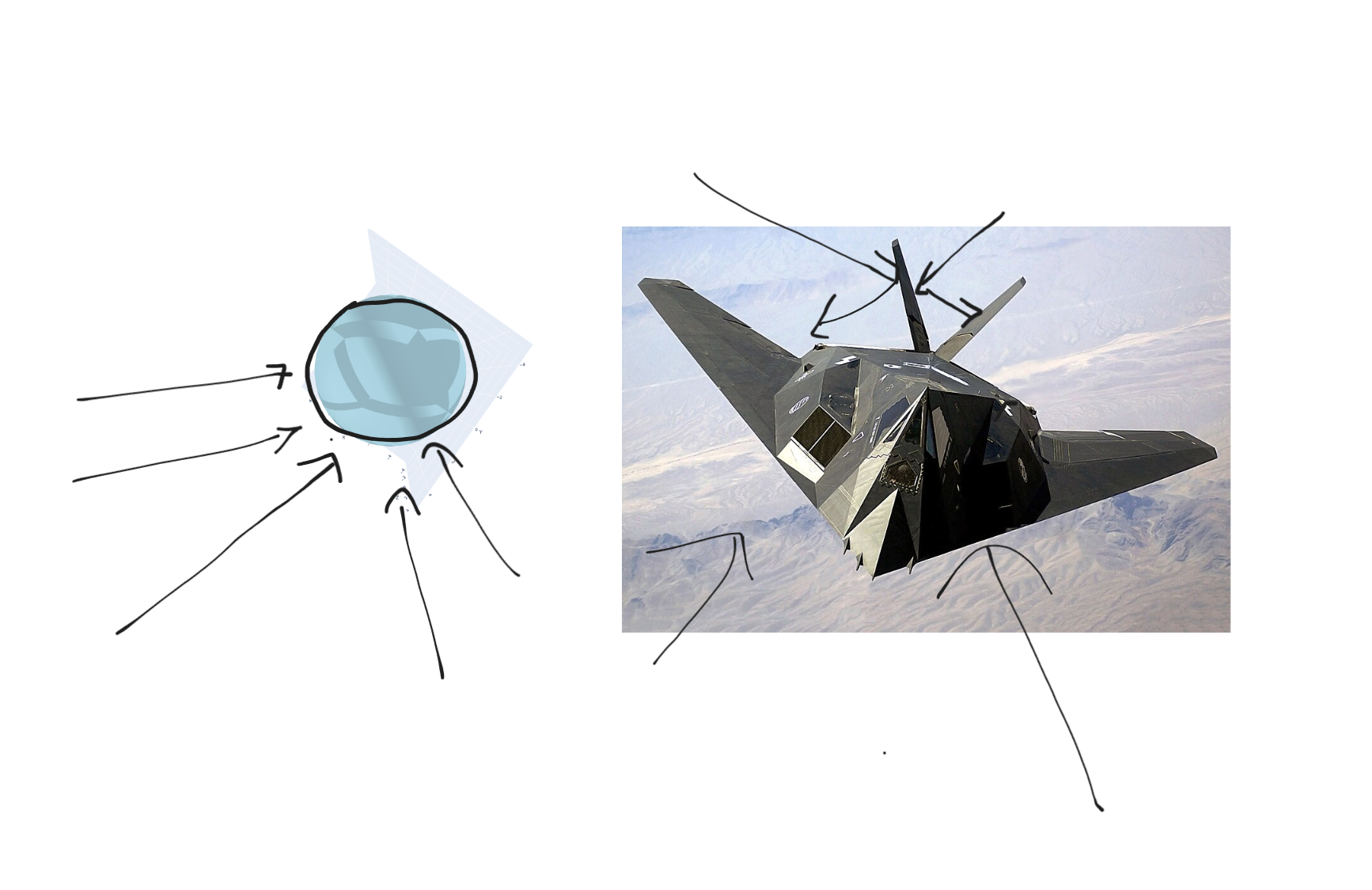
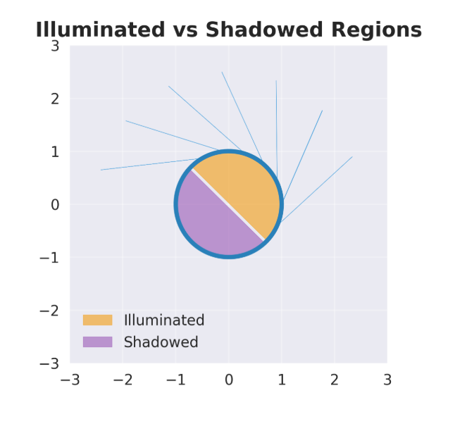
 - Only the illuminated (front-facing side contributes: If a facet is not on the side fo the object directly hit by the radar wave, completely ignore it. This cuts computation into half (or more), and you no longer need to model complex interactions or reflections where a wave creeps onto the other side of the obect.
 1752310428680_qyt61x.png
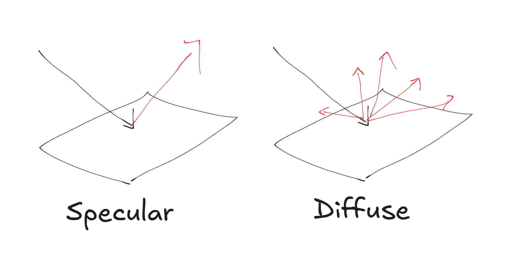
- Fields scatter by specular reflection: reflected waves always bounce off a surface at an angle equal to the incidence angle, like a mirror. This way you never need to model multiple bounces, diffractions, scattering, or anything else messy.
All of these assumptions compromise accuracy. But they vastly simplify the computations, and it turns out that (at least for the time) these simplified models were more than enough to drastically decrease RCS. Now, let's get into the math and see how these assumptions work for us:
For a perfectly conducting surface, the induced surface current density under PO is given (in vector form) by:
where is the outward-pointing unit normal at the surface point , and is the incident magnetic field at that point. This formula basically says the surface current flows in such a way as to cancel the tangential magnetic field on the surface, and the factor of 2 comes from the reflected field adding to the incident field just at the surface.
Now that we know what the surface current is, we can get the scattered field in some arbitrary direction by just integrating those currents over the surface :
This is probably the most important equation in Physical Optics, so let's dive into each term:
- is the wave number (with the radar wavelength). For example, X-band radar at 10 GHz has cm, so . is the impedance of free space, a constant that relates electric and magnetic fields in air. is the direction of the incoming wave (from radar to target) and is the direction of the scattered wave (from target back to radar). For monostatic RCS (the usual case we care about), is just the exact opposite of (since the radar emits and receives from the same location).
- The integrand is a vector that essentially picks out the component of the surface current that radiates towards the radar. (If you recall from antenna theory or the physics of dipoles, a current element radiates perpendicular to its direction; this double cross product helps enforce the right polarization of the reradiated field towards the receiver).
- The exponential term is a phase factor. It accounts for the path difference: if one patch of the surface is a bit farther or at a different angle relative to another, their re-radiated waves will arrive out of phase. When we integrate, these phase differences cause interference that can cancel or amplify scattered waves in certain directions. This is exactly like adding up many small phasors (little arrows of rotating complex numbers) for each surface patch. The integration is only over the illuminated portion of the surface, . If a part of the object is facing away from the radar (in shadow), PO assumes it has no induced current (since the incident wave doesn't hit it directly). This is an approximation, because in reality shadowed regions can still scatter via diffraction around edges, but PO ignores that (one of its known limitations).
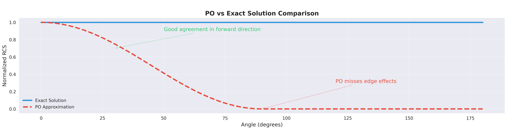
This method is fast and reasonably accurate where the frequency is high and the object is large compared to . The aforementioned limitations (edge diffractions, creep waves) can be significant, and the original "Echo 1" program went back and added edge diffraction modeling when they realized its importance. In my project though, I stick to the basic PO model, which should be enough to capture most of the primary effect.
 1752312201386_d3vzw4.png
PO becomes less accurate the farther the radar angle strays from head-on. fortunately, for aircraft optimization, this was usually acceptable
1752312201386_d3vzw4.png
PO becomes less accurate the farther the radar angle strays from head-on. fortunately, for aircraft optimization, this was usually acceptable
Why facets?
 1752355473770_quokq2.jpg
A natural quesiton to ask at this point is why this plane is so jagged. It's important to note that a core insight from optimization of the PO principle was that flat and angled surfaces are excellent for stealth. Let's unpack this a bit:
1752355473770_quokq2.jpg
A natural quesiton to ask at this point is why this plane is so jagged. It's important to note that a core insight from optimization of the PO principle was that flat and angled surfaces are excellent for stealth. Let's unpack this a bit:
- Remember, one of the key insights of PO is that a surface will reflect radar much like a mirror reflects light (specular reflection). Thus, any flat surface can deflect radar energy away from the source by simply angling it away from it.
- Rounded surfaces: One might expect that a sphere would be near optimal for stealth (I certainly did). But if you imagine a disco ball scattering light, no matter where you are, some part of the curved surface will send light back to you.This is what gives disco balls their characteristic glints, and an identical effect happens on radar. Thus, for stealth spheres are actually the worst-case scenario.
- Internal reflections - if you imagine a completely optimal radar object, it would entirely reflect energy away from the angle of whatever source it came from. Thus, at a microscopic level, it should look like planes of flat mirrors, all angled away from the source (ideally perpendicularly). Imagine this as shining light as a mirror, as in our disco ball analogy. If the mirror is angled away from you, not much of the light you're sending out will return.
 1752311938819_bzcici.png
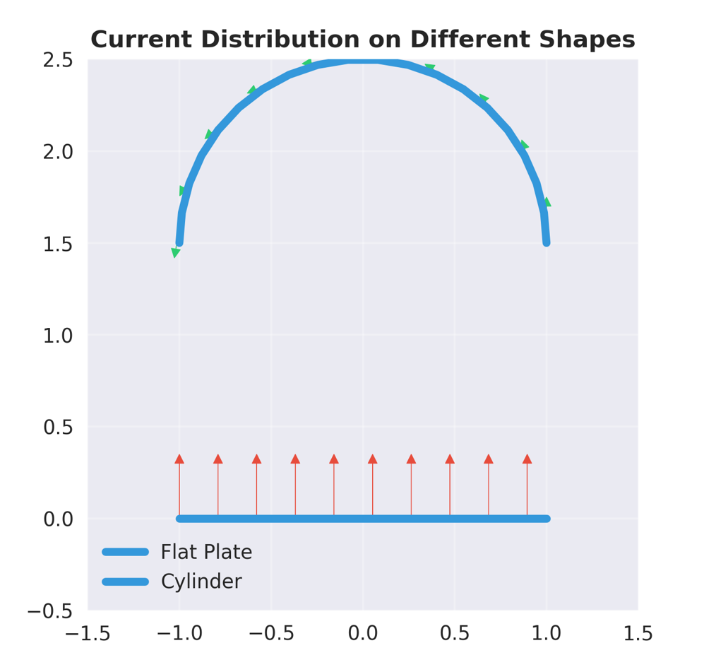
Flat surfaces produce aligned currents and controlled scattering; curved surfaces cause varying currents and increased backscatter.
1752311938819_bzcici.png
Flat surfaces produce aligned currents and controlled scattering; curved surfaces cause varying currents and increased backscatter.
There is a concrete mathematical view for this as well: if we look at the integral above for , we can see that varies linearly along a facet, but nonlinearly along curved surfaces. Local curvature can lead to increased backscatter, and scatter energy in unwanted directions.
The tradeoffs
Flat angled surfaces are not particularly good if you need something to fly; there's a reason no cars or planes are designed as rectangles. The F-117 was somewhat affectionately referred to as the "Wobbly Goblin" due to its strange shape, and the fact that it was inherently unstable7, requiring a computer system to even stay airborne.
Next up
Now that we've got a decent bearing on how the math works, I'll walk you through a recreation of a program like Echo 1 I created this weekend, using modern libraries and a few computing tricks. This article is getting kinda long though and I'm getting rather tired, so I'll save it for a new one
Hope you enjoyed!
Footnotes
-
P. Ya. Ufimtsev, Method of Edge Waves in the Physical Theory of Diffraction. FTD translation HT-23-180-71 (1971). ↩
-
D. Jenkins, Flying the Black Triangle, AIAA 2018 — overview of f-117 development citing overholser’s insight. ↩
-
E. Knott, J. Schaeffer, M. Tuley, Radar Cross Section, 2 e, Artech 2004. ↩
-
FAA, Radar Handbook, chap 3 — human target cross-section. ↩
-
B. Rich & L. Janos, Skunk Works, Little Brown 1994, ch. 12 (rcs figures for sr-71, f-117 development anecdotes). ↩
-
National Museum of the U.S. Air Force, f-117 fact sheet (public rcs range estimates). ↩
-
J. Correll, “History of Stealth,” Air & Space Forces Magazine, Sept 2019 — computing limits, faceting, edge-diffraction fixes. ↩